Showing posts with label boat upgrade. Show all posts

Monday, January 8, 2024

A 15" Touchscreen Chartplotter for around $500?

 First a belated Merry Christmas and Happy New Year everyone!

My boat came with a Garmin 4208 chartplotter.  Unfortunately, the prior owner(s) did quite a hack job installing it and, as a result, there was a rather large and unsightly open hole in the hull behind the unit.  This hole prevented me from ever removing the chartplotter from the helm as it was the rain shield.  Well, a chartplotter is an expensive umbrella, and after having spent many years acting as such, it began having some issues.  The case seal had failed and allowed moisture to enter. Best I can tell, this caused a light film of mold to start growing in the screen and was slowly making it unreadable.  It was time to find a solution.

The Old Garmin Plotter,
as installed by prior owner

I could have bought Garmin's current replacement unit for around $3000, and would have the same functionality that I had.  There were a couple problems with this.  Since my depth, wind, and autopilot are Raymarine, they did not like talking to the Garmin.  Being from the aviation world, I'm also not a big fan of Garmin (particularly after they charged me over $150 for a 32 MB data card while standard 1GB SD cards were selling for around $20).  While talking with the harbormaster at my new marina, he was telling me about Openplotter and how he and others had built their own chartplotters using a Raspberry Pi computer and a few other inexpensive electronic bits.

Who cuts a hole like this?

Fixed, with a mount and connectors
for the new touchscreen

I did some research and decided that it would be worth the effort to try and build my own chartplotter using Openplotter.  If successful, I would have a nice chartplotter that would be capable of integrating the information from the Garmin radar, Garmin sonar, Raymarine wind, Raymarine depth, and Raymarine autopilot without having to replace all of this equipment with items from the same maker.  I could also add a 15" touchscreen interface, AIS receive functionality and, the best part, this would cost me only a fraction of the cost of a complete solution from any of the big name marine electronic manufacturers (a 16" Garmin package would likely run over $7000 by the time all was said and done).

So, for this experiment, I purchased the following:

  • A Raspberry Pi 4 w/4GB memory, case, data card, fan, and card reader $125
  • 15" touchscreen display $120
  • Outdoor VESA mount for monitor $23
  • 3 64 GB micro SD cards for programming and backup $20
  • 12v powered USB hub (for connecting and powering peripherals $20
  • A USB GPS antenna that outputs NMEA sentences $20
  • A Berry IMU gyroscope/compass/acceloremeter chip $38
  • USB RS485/422 converter (for NMEA output) $18
  • RTL-SDR Radio (for AIS receive) $33
  • VHF whip antenna (for AIS receive) $10
  • Opticoupler (for SeaTalk input) $8
  • 2 128GB USB flash drives (for chart/data storage) $25
  • 12v to 5v USBC power supply $12
  • Various cables, connectors, fuses $80
Installing the OpenPlotter software package is pretty easy.  You download the Openplotter image for Raspberry Pi and use an imaging tool to copy it to the micro SD card.  You then insert the MicroSD card into the Pi, hook up the monitor and boot it up.  In order to program and modify things, I also used a Bluetooth keyboard that I was able to add once the Pi booted up.  Then the fun really started.

A touchscreen at the helm
(had to add an anti-glare screen protector)

I won't go into all the details on how to setup OpenPlotter as there is a fair amount of information out there already and it all depends on what sensors and equipment you are trying to connect.  I actually started work on this at home, and overall it took me several months worth of occasional tinkering plus the actual installation on the boat.  But, if you are considering taking on a project like this, I do have a one bit of advice.  Buy a couple spare memory cards for the Raspberry Pi.  You will want them to make backups.  I would suggest keeping two different backups, one for every major milestone and another for more often created backups.  This way you will have options for going back to two points without having to start over.  There were a couple times during my work where a bug was introduced but not noticed until several changes later.  If I didn't have the major milestone backup, I would have been unable to back up to the point before the bug was introduced.

Another thing I didn't realize was that the Raspberry Pi, at least at the time of writing this, does not support the equivalent of a "right click" for touchscreens (either a long-press or double tap).  Since OpenCPN is difficult to use without the right click, I had to find a solution.  I found there is a software driver called Twofing that converts a two fingered tap into a right click.  I installed and configured this driver and was able to right click on things by tapping two fingers on the screen on either side of the item I wanted to right-click on.

I setup the Raspberry Pi to automatically start OpenCPN on boot such that it takes up about 75% of the screen real-estate and another package called Kip to display the information I wanted and is typical of a chartplotter on the other 25%.  The Kip package is actually a configurable web page and can display basic numeric and text data, graphs and gauges, and has a nice compass rose that can display wind speed, direction, laylines, and direction to your next waypoint all on a single dial.  It can display any data that is collected by the system.

Plotter interface in Day mode

...and in night mode

I've still got a little work to do, but so far I am very happy with the results.  The Raspberry Pi gets position information from the USB GPS receiver, wind and depth information from the Raymarine Seatalk connection, AIS information from the RTL-SDR card.  An OpenCPN plugin supports the Garmin HD radar and utilizes free NOAA digital charts and even Explorer charts for the Bahamas (and other areas) from O-charts.  Routes are finally able to be output via NMEA 0183 to the Raymarine autopilot, and I even have pitch and heel information from the IMU. Using a GRIB file downloader, I can load and display weather forecast information overlayed on OpenCPN charts. I can also connect wirelessly to the Raspberry Pi and monitor the boat using my cell phone or a tablet.  And one more added bonus, with the 128GB memory stick, I not only have enough storage for charts, but can also use it as a media server/player...so much of my music collection can be streamed to my Bluetooth enabled stereo. 

The two items supported by the old Garmin that I don't have working are the XM radio and the Garmin sonar.  Although I haven't removed the XM unit, I've never used it and thus far I don't have any intention of using it.  I am unaware of any existing support for the sonar and when I have more time will look at writing a plugin or app to interface and decode the data sent from it (I do see the sonar data on the Pi, just don't know what to do with it yet).  I should be able to at least get depth information from it, if not a full sonar image with fish detection, etc.

The one thing I may change is the touchscreen I am using.  Since this was essentially an experiment, I didn't want to throw too much money into it without knowing how well it was going to work.  I thought the screen I chose would be bright enough to be daylight readable, but I didn't take into account all the reflected glare onto a shiny touchscreen.  The first time I tested it with the sun behind me, the shiny surface made a better mirror than display.  I added an anti-glare screen protector that has helped a lot, but would also like if the screen was brighter.  I know there are brighter screens out there, but they will increase the price of this project a bit.

I will say that, if you are not comfortable with computers and soldering and playing with electronic internals, this project may not be for you.  There is a lot of fiddling with hardware and configuring software involved.  There is nothing that is too complex (except for possibly the sonar, I didn't write any code beyond the script to automatically start the interface the way I wanted it), but there are a lot of individual pieces that need to be setup to work together.  If you are comfortable with these tasks, you can make yourself a very capable chartplotter using well developed and free open-source software.

Thursday, November 23, 2023

Adventures in Refrigeration

Refrigerators in boats aren't typically like those at home.  Unless you have an endless supply of power, you need one that is a bit more power efficient.  In my case, the refrigerator cabinet is a large, fairly well insulated cabinet that opens at the top (like a good portable cooler) and has a divider inside that splits the space into a freezer section and refrigerator section.  The "cold" in the freezer is provided by what is called a cold plate system. There are two metal plates filled with a liquid that will freeze when the refrigeration compressor runs and then they slowly absorb the heat.  Think of it kind of like a block of dry ice that is repeatedly re-frozen to keep the freezer cool.  The refrigerator side of the cabinet is kept cool by allowing some of the heat from the refrigerator side to passively bleed over into the freezer through a couple holes in the divider between the compartments.  

Freezer and Refrigerator Controls

This works OK,  but has a couple issues. The temperature of the freezer plays a large part in the temperature of the refrigerator.  Both the refrigerator and freezer are colder at the bottom than at the top.  If you open the refrigerator much, the refrigerator side can warm above safe temperatures and take a while for the spillover air to cool it back off.  Conversely, if you don't open it enough, things can freeze in the refrigerator side, particularly at the bottom.  And while I like a cold beer, frozen ones can  be an issue. And finally, my freezer could only reach a low of around 15° F (ideal is near 0°F).

One more issue, specific to my fridge, is that the genius who installed it placed the expansion valve (the point in the refrigeration circuit where the cold starts to be generated) outside of the refrigerator cabinet.  This valve freezes and thaws with each refrigeration cycle and therefore condenses water out of the air and makes a big wet mess in the cabinet.  

Other than some of the issues above, my refrigerator did work OK, until the last few trips.  The refrigeration compressor started developing an issue where it would try but fail to successfully start up until after a random and increasing number of attempts. This caused the freezer to warm to unacceptable levels at times. After some investigation, I could only narrow it down to either a failure of the controller or the compressor.  Since those components make up the majority of the system, the system is over 30 years old, it was showing a fair amount of corrosion, and I wanted to correct that installation problem, I decided to bite the bullet and replace the entire system myself.

The old cold plate configuration

This may seem like an excessive step to take, but new systems come pre-charged with refrigerant and special connectors so they can be done as a DIY projects.  Given the difficulty I've had in the past hiring "professionals" to come work on the boat, I actually thought I will either break even or come out ahead...and I wouldn't have to be at the mercy of a "professional's" schedule. So I did a little research and decided I would replace the refrigerator with a newer version from the same manufacturer (SeaFrost).  A similar system should at least minimize the complications of the install.

Replacement System
(image from SeaFrost)

Of course, as often happens with projects, what started out as a simple swap-out of the old system for a new one and the relocation of the valve location slowly grew with several of those "while I'm doing this, I might as well..." thoughts.  The freezer would freeze, but not quite cold enough for ice cream.  Ok, actually, the colder the better for all longer term food storage...but ice cream would be nice too.  When talking with the SeaFrost salesman, it didn't take much convincing for me to upgrade from the smaller equivalent replacement to the next step up with a bit higher capacity.  The upgrade also had the ability to control compressor speed, so I could turn it down and and achieve the same results as the smaller system while using less power.  The existing system had the cold plates mounted in an L shape along adjacent walls, and the salesman highly recommended moving one plate so the two would be on opposing walls for more even freezer temperatures (stuff in the freezer would be sandwiched between the plates).

The old fridge removed

Naturally, if I could get the freezer colder, this would likely exacerbate the problem of the beer freezing in the bottom of the refrigerator.  So I began to think about how to solve that issue.  I had heard of others using small fans to mix up the air so the cold wouldn't settle at the bottom. I also thought of adding some sort of movable shutter to manually control how fast the "spillover" between the freezer and refrigerator would occur.

Patching holes and installing
a new cold plate

I finally settled on a theory that wasn't too mechanically complex and I believed would solve several issues.  My theory was that I would plug the two holes at the bottom corners of the divider, I would construct a small duct on the refrigerator side of the divider that would route the air from the hole about 1/4 of the way up the wall to near the top of the refrigerated section, and I would put a fan at the top of that duct that would pull cold air from the freezer and dump it out near the top of the refrigerator. I would leave the gap between the refrigerator lid and the top of the divider alone to allow return airflow.  Since warm air rises and cold air falls, I figured this duct would limit the majority of the spillover without a mechanical shutter to close the hole.  Then, when the fan was turned on, it would draw the cold air from the freezer up the duct and spill it over the top of the refrigerator.  As the cold air fell down through the refrigerator compartment, the warmer air of the fridge should rise and the pressure differential caused by the fan would cause that warm air to enter the top of the freezer section to be re-cooled.  This mixing should also make the temperature more consistent from the top to the bottom of the refrigerator. And by drawing the cold air from the higher point in the freezer than the very bottom, there would be a section at the very bottom of the freezer where the coldest air would still pool and become a deep freeze section that wouldn't be impacted by the bleeding off of cold air for the refrigerator.

New plates installed with valve
inside refrigerator box

I'm no thermodynamics expert, but this all sounded reasonable to me. So I decided to give it a try.  I installed the new refrigerator...which takes much more time than that one sentence gives it credit for.  Carefully bending copper tubing so it doesn't kink, by yourself, while working in cabinets where you can barely reach what you are working on is not trivial.  Then I found a vinyl (PVC) downspout at the local home improvement store that I could cut into a U shape and create a duct.  Estimating that the refrigerator section was around 5 cubic feet, I ordered a fan that would move about 2 cubic feet of air per minute.  This would theoretically do a complete air exchange in the empty cabinet in about 2.5 minutes.  I figured there would be a balance that would need to be figured out between taking cold air from the freezer too quickly and cooling the refrigerator too slowly, so this was my best guess at a reasonable flow rate.

Testing the duct

In order to experiment a bit, I temporarily sealed the lower corner holes (and the wire/line access hole) with excess packing materials, built the duct using some PVC glue, and ordered a small dual-bearing computer fan and a digital temperature controller for it.  I ran experiments and found that I did seem to have positive control over the refrigerator temperature.  With the freezer at about 15° F at the time of the test, I set the other controller to turn the fan on at 37°F and off at 36°F. The temperature in the refrigerator would slowly fall when the fan was on (about 30 minutes to go from 37°F to 36°F) and would slowly rise when it was off (about an hour to rise from 36°F to 37°F).  I also checked the temperature at several levels within the refrigerator compartment and found only 1 degree of difference between the top and bottom.  During the tests, I did not observe any noticeable rises in the freezer temperature beyond the normal operation.  I did run the tests with both the fridge empty and with several milk jugs filled with water to simulate a partial refrigerator load.

Fridge duct with fan installed

Happy with the results, I made the changes permanent.  I did make one additional change and lined the lower half of the duct with some thin, foil backed, closed cell foam insulation to help further reduce unwanted bleed over.  After warming the refrigerator cabinet back up, I attached and sealed the duct with silicone, cut foam to make removable seals for the bottom corner holes, ran the wires and temperature probe needed to control the fan, and sealed the cabinet access.  I added a magnetic switch in the fan circuit so the fan would shut off when the lid was opened, and I installed a small electrical project box to hide the connections and extra wire from the fan and switches.  

So far I'm pretty happy with the results.  The only thing I'm wondering right now is if I need to increase the size of the fan to improve the speed at which the refrigerator section cools.  But I think I need a bit more experience with the current behavior before I make any changes.  I can also probably tweak the settings of the temperature controllers for both the refrigerator and freezer sections; however, this will be done slowly over time as I determine a sweet spot once the whole system stabilizes.  The first picture above is the system running with the freezer and refrigerator cabinet temperatures displayed.

I'd also like to give a shout-out to the folks at SeaFrost.  They were very helpful with advice and design recommendations on this project.  I wish more marine industry parts and service suppliers were this helpful and responsive.

Now I have a reliable refrigerator/freezer that acts a bit more like a home system than it does the normal boat cold plate system.  

Monday, May 4, 2020

New Sunroom

After building the hardtop for the boat, one of the next items needed was a replacement dodger.  For those that don't own a boat, the dodger is essentially the front windshield for a boat.  It isn't strictly necessary as, unlike a car, you aren't cruising along at speeds fast enough that something flying in from the front isn't likely to cause injury...but anyone that has spent much time at the helm of a boat on a less than perfect day may disagree.  When we completed the hardtop in Virginia it was around Christmas and we were in a hurry to head to warmer locations.  At the time I jury rigged the old dodger so we would have at least minimal protection.

The jury-rigged temporary dodger.
During that cold and rainy trip south, it became very apparent that just a simple dodger up front wasn't really sufficient to protect someone at the helm from bad weather.  The cold rain always seemed to be blowing in from the starboard side and that made manning the helm a miserable experience.  So, back before this virus when I was looking at heading to the Bahamas in February, a better dodger and side protection...at least for the starboard side...was very high on the upgrade list.

Having an enclosure made was not going to be an option as that would be too costly for something just to improve comfort for the upcoming trip (small sailboat enclosures usually cost more than $4000 and I'm sure mine would be much higher due to the size).  A while back we purchased a Sailrite sewing machine and part of the justification of that purchase was to tackle projects like this.  My goal was to create a cost effective and serviceable solution that could be used when needed and taken down most of the time. Just like the hardtop, this would be my first time attempting to create something new for the boat, so higher end materials were less of a concern.  If I really screwed things up, at least I wouldn't feel as bad about it if the materials didn't cost a fortune.

First thing was to come up with a design. At first blush, it seems like a fairly straight forward process...create some fabric and clear vinyl panels that would enclose the front and at least part of the sides of the cockpit.  Of course, the devil is in the details.  I wanted to utilize the existing lower mount for the old dodger and then there was what to do about the sheet winches that are right in the middle of where enclosure panels would normally go.  Ideally, having all the winches inside the enclosure so you can stay dry while adjusting sails would be good, but in the end I could not figure out a way to make that happen.  In the end I came up with a design for a front panel and two smaller side panels that would wrap around behind the winches so that one could at least operate the winches with the panels in place.  I also planned for partial panels along the sides so the helm would be protected.

From there I came up with an estimate of how much clear vinyl and material was needed for the project.  5 yards of vinyl and 4 yards of material looked like it would be enough.  Checking online, I was able to find a supposedly marine grade vinyl for about $85.  Sunbrella, on the other hand was about $25 to $35 per yard.  I decided to check a discount fabric store in nearby Wilmington and found they had a roll of Sunbrella in an off-white color that just about perfectly matched my gel-coat for $17 at yard.  Another $100 worth of zippers, snaps, thread, pattern material, and other sewing notions from Sailrite as well as reusing a few zippers from the old dodger and it looks like I could make an enclosure for around $300.  On that trip from Virginia, I'm sure my wife and I would have gladly paid $300 for the added comfort of a dry helm out of the wind.

Creating the dodger pattern.
After watching and re-watching several of the how-to videos from Sailrite, I began the process of creating patterns for the front dodger. Of course, creating patterns by myself, outside, in the wind was a bit of a challenge. Trying to get the plastic stretched tight and marked before the wind would come along and blow it all down took several tries and in the end was not perfect...but good enough. Creating the dodger in the salon, when the dodger spans the distance across the salon and galley was an interesting task.  I cut the Sunbrella material into the numerous strips I needed using a straight edge and wood burning tool. Fortunately some of the tricks I picked up from the how-to videos as well as judicious use of the Sailrite seam-stick basting tape for canvas helped a great deal with the assembly and sewing tasks.  After a lot of sewing, I had a new dodger that took advantage of the extra viewing area afforded by the new hardtop.

Cutting long strips of Sunbrella
Next came the two small panels that ran behind the winches.  It was a pretty straight forward process to pattern and create those small panels out of the Sunbrella material.  These panels extend past where the existing mounting hardware was, so I had to add snaps to hold the bottom of the panels.  While on the Sailrite site I found that they had a new type of snap called a Snad that utilizes 3M VHB tape so I wouldn't have to drill holes in the hull for conventional snaps. The only downside to the VHB based solution that I've found thus far is that it takes up to 72 hours for the snaps to fully bond to the surface.

Sewing the dodger.
After getting the winch panels done, I realized I actually had enough material to make full side panels for the cockpit instead of the half-width panels that I originally planned to make.  I was having a difficult time determining how to best secure the half panels, so this solved that problem...but created another.  Snaps were less likely to hold such a large panel in place in the wind so I had to come up with another solution to attach the panel to the arch.  While trying to figure out the best way to attach the panels, I went ahead and created the panels.  When I made the hardtop, I included a design element that would hopefully aid in the installation of a full enclosure.  The bottom of the "handrail" edge around the hardtop can be slit at the bottom creating an awning track.  This track would then allow for installation of enclosure panels using a pre-manufactured bolt rope that slides into the slot. The solution for holding the panel to the arch is essentially the same solution.  I took the old awning track that came off of the arch when I installed the hardtop, cut it in half, and attached the segments to the arch.  One more zipper per panel and more of the bolt rope, and viola, the panel is attached.  The boat now has a 3/4 enclosure, with the back left open.


The end result isn't perfect, but it is functional and doesn't look too bad.  The vinyl isn't as optically clear as the expensive stuff (it has minor distortions that I think are due to the manufacturing process) but it is good enough and well worth the trade-off for keeping warm and dry. If I keep up with the maintenance of the vinyl (regular polish and UV protectant...same as is recommended for the much more expensive vinyl products), I have confidence that they will last a long time and will be a nice addition to the boat.

Wednesday, April 15, 2020

Keeping Busy

At this time I believe that most of the U.S., despite the lack of a federal mandate,  has some sort of restrictions on the gatherings and movement of people in an attempt to slow the spread of the Corona virus pandemic.  Most have some variant of a "stay at home" or "shelter in place" order.  The result of which seems to be a lot of boredom...to the point that people are <gasp!> even cleaning their own homes.  For a boat owner, finding something to do is pretty easy.  I've heard it said many times that if you think there is nothing to fix on your boat, you simply aren't looking hard enough.  In my case, it doesn't seem to take a lot of looking.

I think I've previously written about the work that I needed or really wanted to get done before making the trip.  A few things were known and there were many more that were discovered once I returned to the boat.  In hindsight, it is probably a good thing that there were so many items that resulted in delays to the trip, otherwise my crew and I may well be stuck in the Bahamas right now or figuring out how to make a direct sail back to the U.S.  If you are curious what is going on in the Bahamas right now with regard to boaters, you can click HERE to see the current (as of 4/15/20) situation.

Work on the boat does continue, albeit at a slower pace.  Part of that is due to the fact that it appears I will have a fair amount of time before this pandemic subsides so I'm not in a particular hurry now.  Another reason is that getting supplies has been complicated by the COVID19 pandemic response and other issues. There is also the conflict between the need of help for some tasks and physical distancing requirements/recommendations. 

The first delayed project has been the rigging.  Getting the rigging at a price that wouldn't scuttle the trip before it started was one of the first delays.  Now that I have the rigging, social distancing and travel restrictions prevent any further progress on that task for the time being.

The rigging finally arrived.  180 lbs or so.
Unable to find a suitable replacement dinghy at a reasonable price, the decision was made to try and refurbish my well sunburned dinghy.  Patch material, refurbishing paint, and replacement valves were ordered.  The patch that has leaked for as long as I have owned the boat has been re-patched and now holds air and another patch has been applied.  Initial base coats of the rubber paint has been applied and the dinghy now looks significantly better and holds air.  Unfortunately more base coat was required and the new can was found to have been partially solidified when it arrived, therefore a replacement had to be acquired.  It finally arrived yesterday, so naturally it is cold, rainy, and windy outside today.  But progress will continue on that project.

Dinghy original condition.

Dinghy after first base coats of restoration paint applied.

The partial cockpit dodger/enclosure was a project that I had planned to do before getting to the boat.  A trip my wife and I made from Virginia to Southport in early January, just after completing the hardtop build, emphasized the need for protecting the helm from the weather.  The front dodger was created a little while back and is up and functional.  After completing that part, I found I had enough material to do complete panels for the sides, so I altered the design and created those side panels.  Unfortunately, I was lacking a couple of zippers to complete the build and those arrived only a couple days ago.  So, that project is almost complete, again just waiting on the weather so I can do a final fit and determine the exact position for attaching the zippers and a couple additional snaps. 

Test fitting enclosure panels.
Since it appears that I will be on the boat for a while as the temperatures rise here in North Carolina, I decided to revisit continuing issues I have had with the raw water pump for the air conditioner.  After several attempts to repair the existing pump, the motor finally seized up and a replacement had to be ordered.  As is my usual luck, despite ordering the correct pump, the one that was shipped to me was not a 115 volt A/C pump but a 230 volt one.  That had to be returned and the correct one re-ordered from a more trustworthy supplier than Amazon.  The replacement arrived about a week later and was installed and I'm happy to report that the air conditioner is again operational.  Hopefully it will stay that way for a while.

My boat was a former charter boat and was equipped with several 115 volt AC plugs, but only one 12 volt DC plug.  Since the native boat power system is 12 volt DC, it is rather inefficient to convert power from the 12 volt battery bank to 115 volt AC using the inverter and then back to  DC voltage to power things like phone, radio, and flashlight chargers.  I have now installed two new 12 volt DC sockets to provide a more efficient means of utilizing the house battery power.  With the earlier addition of solar, the boat is now more self sufficient than ever before.

New 12 volt socket with USB charger in it.
There are other projects that I initially intended to defer until after the trip that are now getting some attention while I have time.  I wasn't happy with the velcro that was used when I initially recovered the salon cushions and have since reworked those covers.  I'm continuing to retrofit some of the lights with LED strips to further  lower power consumption.  I've finally managed to identify one of the leaks the boat had during heavy rains and will be looking at repair options for it.

Social distancing and my lack of desire to go to stores any more than absolutely necessary has also given me a chance to use supplies and practice techniques that come in handy when living in a remote anchorage or on passage.  Learning better techniques to store various fresh vegetables and what can be easily frozen to extend shelf life is a continuing process. I'm also getting better at controlling the boat oven for baking more delicate items like breads.  I've even tried Nido powdered milk that came recommended at The Boat Galley and have to admit it is almost as good as fresh and certainly suitable for baking and as a coffee creamer.

Speaking of not wanting to go out shopping, since I have a sewing machine handy, I offered to sew masks for the local hospital if they were in need.  Thus far, they have not indicated a need, but I am on their list of people to contact if the need arises.  I did create a couple masks for myself for if/when I need to go to the grocery store.  One of the other boaters here at the marina has a daughter that has an immune disorder, so I also made a couple masks for them. It was an interesting exercise to try and figure out materials I had on hand that would make a reasonable mask.  What I found was that non-woven fabrics were generally considered better than woven fabrics for trapping smaller particles.  What I ended up using for my own design (again, with what I already had on board...which was very limited) was the non-woven material used in some types of reusable shopping bags for the outer layer and a cotton bed sheet for the inner liner.  Since I have a spool of stainless steel safety wire, I used pieces of it to create the bendable nose bridge.  Although I can make no guarantees about the effectiveness of the masks, I'm reasonably confident they are far better than nothing. 

So, in these strange times, I continue to keep myself busy.

Monday, February 17, 2020

Power of the Sun


As I eluded to in my last post, there is one project, or upgrade, that made the list along with the repairs, and it is something that I had wanted to do since before we built the hardtop. When Doug, my crew that came to help out with some of the repairs on the boat, came up with a system that wouldn't cost too much more than the fuel I anticipated we would use with the generator on the trip (at Bahamas prices), I decided it was a worthwhile investment.  I'm, of course, talking about adding solar power to the boat.
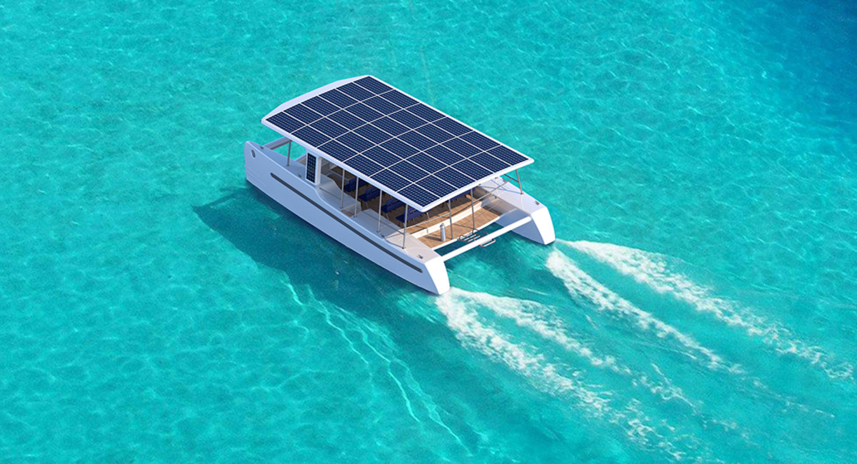
SoelCat 12, an autonomous solar electric catamaran
No, this is not my boat.

When I was designing the hardtop, I intentionally moved the sail viewing window forward just a bit in order to allow for the larger size panels you often see in residential applications as well as building in wire chases that could be used for solar.  At the time, getting panels for around $1 per watt was a very good deal.  Now the power output has increased and prices have fallen and you can get 320 watt panels that should put up with the marine environment for under $0.60 a watt.  He also found a MPPT solar controller that was getting pretty good reviews for $150.  A couple lengths of 6 gauge wire from the controller to the batteries, the special 10 gauge wire for hooking up the panels, a couple breakers, a wire gland for sealing the wire chase hole in the hardtop, a special tool for installing weatherproof MC4 connectors on the wires, and a couple other odds and ends for installation and I'd get "free" power from the sun.  Since Doug would be passing nearby the solar panel supplier on his way to the boat, it would also save me the (not insignificant) shipping cost for the panels.  The whole system would end up costing me around that magic $1/watt number that used to be reserved for just the panels.

The first step in the process, after getting all the materials to the boat, was to drill new holes in my beautiful hardtop.  Having worked so hard on that top, I had mixed emotions about drilling 5 holes for each panel in it...but if I wanted solar it had to be done.  We brought one of the panels to the boat, attached the mounting brackets to it, and marked the four mounting hole locations for each panel.  We carefully determined where the middle of the wire chase was on the underside of the top and marked the larger hole for the wire chases.  Using my drill guide, I drilled oversized holes until we reached the bottom fiberglass skin, cleaned them out, filled them with epoxy (the top is foam cored, so I needed to create a sealed "sleeve" for the holes that would also act as a compression post to tighten bolts), and drilled the smaller final size hole at each location.  It all sounds simple enough, but this is a boat project so we had to fight weather, wait for epoxy to cure, as well as other issues so making the holes ended up taking 3 or 4 days to complete.

Carefully locating the center of the wire chase.

While waiting to complete the holes in the hardtop and get the panels mounted, we installed the solar controller, breaker, and wiring from the controller to the battery bank.  The solar controller and breaker were mounted in the engine room next to the original battery charger for the boat. The wiring was run from the large main bus bars below the main electrical panel (think of a bus bar as the extension of the positive and negative posts of the battery bank), through the breaker, and on to the controller.  The controller connection was another interesting problem to solve.  Our calculations showed that we should use 6 gauge wire for the charger, but the charger terminals would fit at most a 9 gauge wire (remember the larger the gauge number, the smaller the wire).  Since the controller is rated for 60 amps, it has two connectors for each of the positive and negative battery outputs and the instructions said to run two wires to the battery...probably done to save in production costs of the charger.  Well, I didn't want to double up wires. It turns out if you take a 6 gauge wire, strip off the cover, divide the wire strands in half, and re-twist them into two conductors you end up with two 9 gauge wires.  So, that is exactly what we did to the end of the 6 gauge wire cable.  Marine grade wire cables use thin diameter strands of wire for the conductor (for added flexibility) so it was a fairly easy process. Seal it all up with quality adhesive lined heat shrink tubing and viola, a custom single cable that hooks up to the controller. A few zip ties and zip tie mounts and the cables were installed.


Drilling and filling holes in the hardtop.

Once all the holes in the hardtop were ready, we mounted the solar panels and sealed the top sides of those holes with butyl tape.  We then used an electricians fish tape to pull wires from each of the solar panels through the unsecured gland boxes, the chases in the hardtop, and to the access panel in the top corner of the targa (arch at the rear of the boat).  There we used two Y adapters to connect the solar panels in parallel and ran the resulting single set of wire down the rest of the arch, into the engine room and over to the controller.

Making the custom connection wires.

After wiring the controller up, were now ready for a test.  Of course, we were ready at about 5pm and the sun was a short time away from setting, so this wouldn't be a real test of power generation, but it would be enough to verify everything is hooked up and working.  We flipped the breaker on the battery connection and the controller came to life and recognized it was connected to a 12 volt battery bank.  A few parameters were set in the controller and then the solar panels were connected.  We have power generation!  It was only about 150 watts coming from the panels and a couple amps going into the batteries (I don't recall the exact numbers), but it was proof that the system works.

Solar controller mounted next to the original charger.

The next day we did a second test.  It was fairly sunny and right around noon and....wait a minute.  It was only showing 150 watts from the panels and under 10 amps going into the batteries.  Oh yeah, need to turn off the regular charger and drain the batteries a bit...it was doing a constant voltage topping charge because my regular charger was taking care of the batteries while I'm plugged in at the dock.  I used the inverter and a space heater to pull some energy out of the batteries and then tried again.  That's more like it.  Even with the boat sitting so that one panel tilts a bit north and the sun was at best about 45 degrees from overhead, we were seeing 460 watts coming from the panels and 31 amps (at proper charge voltages) going to the batteries. Yay!

Data from the Android App.

I finished tidying up the wiring and checked the connections with my non-contact thermometer to make sure there wasn't any resistance causing heat build up.  We then reinstalled all the access panels and I glued down the wiring glands on the top so it is again waterproof.  The only thing left to do on the install is figure out some sort of skirting for the panels so lines don't accidentally get hung up under the panels.

Panels Installed except for line deflection skirting.

In the days since the initial install, I have run a number of other tests and found that, as long as I'm not running electric heaters or air conditioners, the setup seems to keep the batteries charged.  Of course the real test will be sitting at anchor when I have to use the inverter (or...shudder...the generator) for 120 volt AC service. 

I also found a glitch in the solar controller.  It was rarely going into its float charge state.  I contacted their technical support (which only seems to be available via e-mail) and found that the charger has a hard coded value for the switch over point from topping charge to float charge and doesn't take into account the recommendations of most of the battery manufacturers or size of the battery bank.  For most solar installs that have loads that take power most of the time, this isn't really an issue as charging time is limited by sunlight hours.  The only time it comes into play is when the battery is fully charged and there isn't a load (like a boat in storage). I was informed that, at the price point of the charger, the manufacturer would not change the programming of the device to better align with the lead acid battery manufacturer recommendations. Fortunately there is an easy work-around by simply setting the controller to limit the charge voltage to the lower values used for float charging when the system isn't actively used.  With the WiFi feature of this controller, it is easily done.  Not the ideal solution, but good enough for my purpose.

Overall I'm happy with the result.  One of the things I really hated was to have to start the generator in an otherwise peaceful anchorage in order to recharge batteries.  With this addition, I hope I won't have to do that very often.  Not having to burn fossil fuels in order to produce energy is also a good feeling.


Sunday, December 11, 2016

Much Improved Salon

Well, like most projects, the settee cushions took a bit longer than I anticipated. After getting the foam cut and test fit, I started cutting out the fabric. The wood burning tool I used to cut the Sunbrella material worked well, but it is a slow process. Not having the material unravel is well worth the effort.  I used a permanent marker to trace around the plate (top and bottom) patterns of the cushions. The straight boxing (side pieces) were just measured, but patterns were used for the curved boxing of the back cushions. Although the fabric doesn't have stripes per-se, it does have a pattern or grain so care had to be taken while positioning the patterns to make it all look right.

The old, cracking salon cushions.
Sewing the pieces together to make the cushion covers is fairly straight forward and there are plenty of tutorials at Sailrite on how it is done.  The trick was getting the zippers installed along the seams the same way it was done on the original cushions. The trick I found that worked best was to sew the boxing together, then starting about an inch from the end of the back seam, sew a couple inches of the boxing on, placing marks on the material.  I would then temporarily sew the gap in the middle where the zipper would be using the largest stitch possible.  From that, I could position and add the zipper without things moving around too much.  Once the zipper tape was attached, I would install the slider, rip open the seam and sew across the ends of the zipper to lock everything in place.  From there, I could sew the remaining boxing to the plate.

Making new foam inserts for the cushions.

The Sailrite machine works very well for sewing heavy materials and zippers together. Although not a fancy, computer controlled machine, I have no doubt that these machines will last a lifetime even under pretty heavy usage. I think we will be holding onto it even after the boat is gone.

I applied polyester batting to the foam using 3M 77 spray adhesive.  Then began the process of wrestling the foam into the covers.  Since the covers are actually a bit smaller than the foam itself, this can be a bit of a process, but having the foam fit tight makes the cushion look a lot better.

After the bottom cushions were done and test-fit on the boat, I checked the patterns for the seat back cushions. The original back cushions didn't line up all that well, and I hoped to at least improve upon the alignment.  I adjusted the patterns a bit and went to work on the seat backs.  Sewing the large curved cushions was the most difficult as there are no corners to align.  The front plates are longer vertically and shorter horizontally than the back plates.  I had to make center marks and pre-pin the pieces together before sewing them up.

The new cushions. I think they are a vast improvement.

So, it was a bit more time consuming than I thought, but I think the result was well worth the effort.  The new cushions look far better than the old cracked vinyl ones and I think are quite a bit more comfortable too.  Hopefully the new owners of the boat will appreciate them.

Saturday, February 6, 2016

One Less Incandescent Light

A while ago I started converting most of the incandescent lights over to LED. When I bought the boat, there were a number of incandescent bulbs. All the navigation lights and a number of interior lights used incandescent bulbs, so as I found LED alternatives and when lights or fixtures started giving me problems, I would switch them out.

All of the salon lights were 10 watt festoon bulbs and have been converted to homemade or pre-purchased LED bulbs. The navigation lights were converted once I found the right bulbs at a reasonable price.  When the anchor light burned out, it was replaced with an LED.  When the deck light went on the fritz, I found a nice Par LED replacement bulb and replaced it.  The only incandescent lights left on the boat were the reading lamps in the berths (I hadn't found a bulb replacement for them), a couple of cockpit lights (the new top will be getting new lights to replace them), and the steaming light (not a high priority since it is only on when engines are running).

Well, on our trip south, the steaming light went out.  So, I guess it was time to convert that one to LED too. All of the navigation lights on the boat use the same BAY15d base bulb. Of course I couldn't find one in stock in Southport, so I ordered one from the local Napa store that also sells a lot of marine supplies.  I had been using the bright white bulbs in these fixtures, but since I had to order one, I went with the warm white this time.

Why warm white?  Well, it actually has to do with the red/green navigation light. The colored lenses on those lights were designed for use with an incandescent bulb.  When I went to the bright white bulbs, I noticed that the green looked a bit more blue than before (after all yellow + blue makes green). I had heard (after I bought the LED bulbs) that this might be the case.  So, by ordering the warm white bulb, it should help the bi-color light look the right color once again.

The bulb came in yesterday, so naturally it rained all day.  Today it was cooler, but sunny, so it was time to swap the bulbs around.  I removed the bulb from the bi-color navigation light and replaced it with the new one.  I then took the bright white bulb that was in the bi-color light up the mast with me to replace the steaming light.


I wasn't sure what I would find when I went up the mast to fix the steaming light.  With previous light issues on the mast, one was a burned out bulb and another was a bad connector.  So I gathered up a multi-tester, some crimp connectors, pliers, screwdrivers, and my trusty dielectric grease and headed up the mast. The steaming light is protected by a metal cage, and when I tried to remove it, I found the screws were pretty much frozen in place.  They wouldn't budge.  At all.  The screw that I needed to remove in order to remove the cover of the light was positioned right behind one of the bars, but I managed to get a screwdriver to it well enough to disengage it.  Then I carefully removed the cover and lens, maneuvering it through the openings in the cage.

Once I finally had access to the bulb, what did I find?  An intact incandescent bulb.  I removed it, inspected it, and put it back in place.  I asked my wife (since she wasn't hanging off the side of the mast) to go flip the switch.  Sure enough, the light came on.  Whew, it was just a little corrosion on the bulb that caused the outage.  After turning the power back off, I removed the old bulb.  I took out the LED bulb, applied a little dielectric grease on the contacts, and installed it in the fixture. We tested the new bulb and confirmed it worked.  I replaced the lens and cover and checked the function one more time before I headed back down.  All was well.

So, now all the lights on the big aluminum stick have working LED bulbs.  Hopefully the LEDs and the protective grease will make these lights a bit more trouble free for a while, and I won't have to climb the mast for any lighting issues any time soon.

Wednesday, February 3, 2016

Where's The Juice

The house battery bank has become our major task on this stop.  I had hoped we could partially revive the bank and deal with it once we were further south, but it was not meant to be.  Right now one battery has been removed from the bank (suspect an internal short that may have been the cause of the original issue), and the remaining two don't hold much power.

The old battery bank...and some baking soda to neutralize acid

I've been doing research on batteries and have found that many don't consider most of the marine deep cycle batteries to be very good or capable of deep cycles.  Add in the fact that the identical replacement batteries cost $700 each (and I need 3) and spending that kind of scratch on a less than good solution seemed silly.  Golf cart batteries (group size GC2) are generally considered to be much better at deep cycle use, and two of them fit within the footprint of the group 4D batteries (that is the size that currently make up my house bank). They are generally less expensive and have higher amp-hour (Ah) ratings so this decision was fairly easy.

Then came the great AGM versus wet cell debate.  There are certainly pros and cons to both options.  The big pros for AGM are the lower maintenance requirement, low self discharge rate, and faster charging.  The pros for wet cell are they can tolerate overcharging a bit better, seem to have a bit higher capacity, and are cheaper.  To us, it was a real toss up.  The existing batteries are AGM as are the engine start batteries, so we figured we would likely go that route.

That is, until we tried to get some.  The local Napa store didn't have any in stock, and the ones they could get seemed inferior to many others.  The guy at the local golf cart store tried to locate ones from a variety of different suppliers and only found two options.  One he wouldn't be able to get until mid February and the other was over $300 each. On the other hand, he had just received a pallet of 232 Ah wet cell batteries that cost $105 each. We tried looking online for AGM's as well, but between shipping and the inability or cost to ship the old batteries back (cost of batteries usually includes returning the old ones back for recycling...since all that lead is still worth some money) and the resulting core charge we would have to pay (over $200), it wasn't a feasible option.  So, the decision was pretty much made for us...we would go with the wet cell batteries. Since the race between AGM and wet cell was so close in our minds, we really didn't mind this route.

The new batteries

We bought 6 of the US 2200 XC2. These are 6 volt batteries rated at 232 Ah.  By wiring two of these in series, I end up with a 232 Ah 12 volt "battery".  Wiring 3 sets of these in series would give me 696 Ah.  The old batteries were 198 Ah each, so the battery bank, when it was good, was a total of 594 Ah.  This means the new setup will give me an extra 102 Ah.  Of course, for best life you are only supposed to discharge batteries to 50%, so this gives me an extra 51 Ah of usable power.  Not too bad, particularly when you consider the fact that all the batteries cost less than just one of the West Marine batteries.

Of course, the batteries weren't the only cost related to this change.  I needed 3 new cables to connect the 6 volt batteries in series to make 12 volt battery sets.  I considered ordering some custom cables from GenuineDealz (I've purchased wire from them before and have seen their custom assemblies), but being a bit impatient, I opted to have them made locally.  The Napa Auto Parts in Southport stocks a variety of marine grade stuff and that included the 2/0 marine grade wire and crimp on connectors needed to make the cables. They made me the 3 cables I needed for a little under $40.

Getting the old 4D batteries out of their home in the cockpit locker wasn't as bad as I thought it might be.  Doug, the harbormaster at Deep Point Marina, came and helped me lift them out of the locker and get them off the boat and to the car. We put them in some heavy duty trash bags and took them to the battery store to trade them in for the $35 per battery core charge (the golf cart store was nice enough to understand that a 4D battery was roughly equivalent to two "cores" so we could get the 6 core charges refunded with the 3 4D batteries). After getting the batteries out, we had a little cleanup to do.  We ended up using 3 boxes of baking soda and copious amounts of water to clean up the mess we made trying to revive the old batteries.  This took quite a bit of time, but after a few hours the battery box was reasonably clean and ready for the new batteries...or so I thought.

Before I decided to go this way I spoke with a couple of people who owned Leopard 38's and have done this change, and they reported no fit issues.  When I measured the space (as best I could when the old batteries were still sitting in there) it looked like it was going to be close. So, naturally, the batteries didn't quite fit.  I guess my battery box was just a bit smaller than the boats that came after mine, and the two golf cart batteries, when placed end to end, wouldn't quite fit into the tray built to hold the old 4D batteries.  I ended up having to modify the tray so there was enough room. Height was also a minor issue, and I had to modify the ledge that holds the shelf/lid to the battery compartment in order to get the batteries to fit. Not major reconstruction, but not a slide in replacement either.

Minor technical adjustments to the battery box

Finally, after many hours of cleaning and reworking the battery box, the new batteries were placed in the compartment and wired up.  Connections were checked, and after verifying everything looked OK, we flipped the switch and brought the electrical system on the boat back to life.  Before letting the inverter/charger go to work charging the bank, I changed the settings to represent the new battery bank configuration.  Then the charger was started.  It seemed happy with the batteries and charged them up after an hour or so (being new, they were mostly charged when we got them). Since it was getting dark and cold, we decided to finish the last parts of the install in the morning.

The new house battery bank wired up

The next morning I started by running a couple tests to confirm everything was working as it should.  I ran the inverter with high load (our smaller cabin AC unit) and checked temperatures of the batteries, battery terminals, and cables with a non-contact thermometer and only saw a couple degrees of difference after letting the unit run for 15 minutes or so.  I then turned the charger back on and took more measurements to verify everything is fine.

Then came the finish work on the battery box itself.  With the cables attached it took up even more room above the batteries, and I decided I needed a little under an inch of extra height for the lid. I added some wood strips to the battery box lid and mount to give it more clearance for the taller batteries and cables. I also repositioned a couple of the wires to allow better access to the battery vent caps.

Modified ledge so everything fits

The one last hurdle was how to strap the batteries down.  The box had 6 straps and I figured I could use one per battery.  But I didn't take into account the wires and the funky battery caps on the battery.  Simply running a strap over them would hold down the caps so you couldn't open them to add water (a necessary maintenance task on flooded cell batteries) and worst case might even break the caps. I thought about just putting wood blocks on the top of the batteries to hold the strap off of the caps, but I was worried that they could slide and that would result in the straps coming loose.

My solution was to create some wood spacing blocks that would slide in between the battery and tabs of the battery tray and run up the side of the battery.  At the top, a second piece of block was added to sit atop the battery so the straps would hold the batteries down.  This solution will hopefully prevent the batteries from moving side to side as well as allow the straps to hold them down without crushing the battery caps or putting a lot of strain on the cables.

Modified battery box lid and battery hold down shims

Of course, constructing these things and then painting them so they might survive a little while in the harsh environment of a boat battery box has taken a lot of extra time.  The temperatures have been OK here in Southport, but still not good paint drying temperatures. I let the shims dry for a good day, and they still feel just a bit sticky to the touch but I'm sick of waiting.  The batteries are strapped in now and everything is finally back in the locker, and the cockpit is looking a bit more like a cockpit and less like a garage. It has taken me about 5 days to do this battery replacement. I'm still hoping for the day I find a project that doesn't take 10 times longer than I think it should on this boat. But now we seem to have a well functioning battery bank.  Only time will tell if going the golf cart battery route will be worth it.